
SiteRF calculates one transmitter for each enabled radio that participates in the selected scenario. A tri-band access point can therefore contribute separate 2.4, 5, and 6 GHz transmitters, each with its own frequency, bandwidth, power, and gain.
Choose compatible hardware
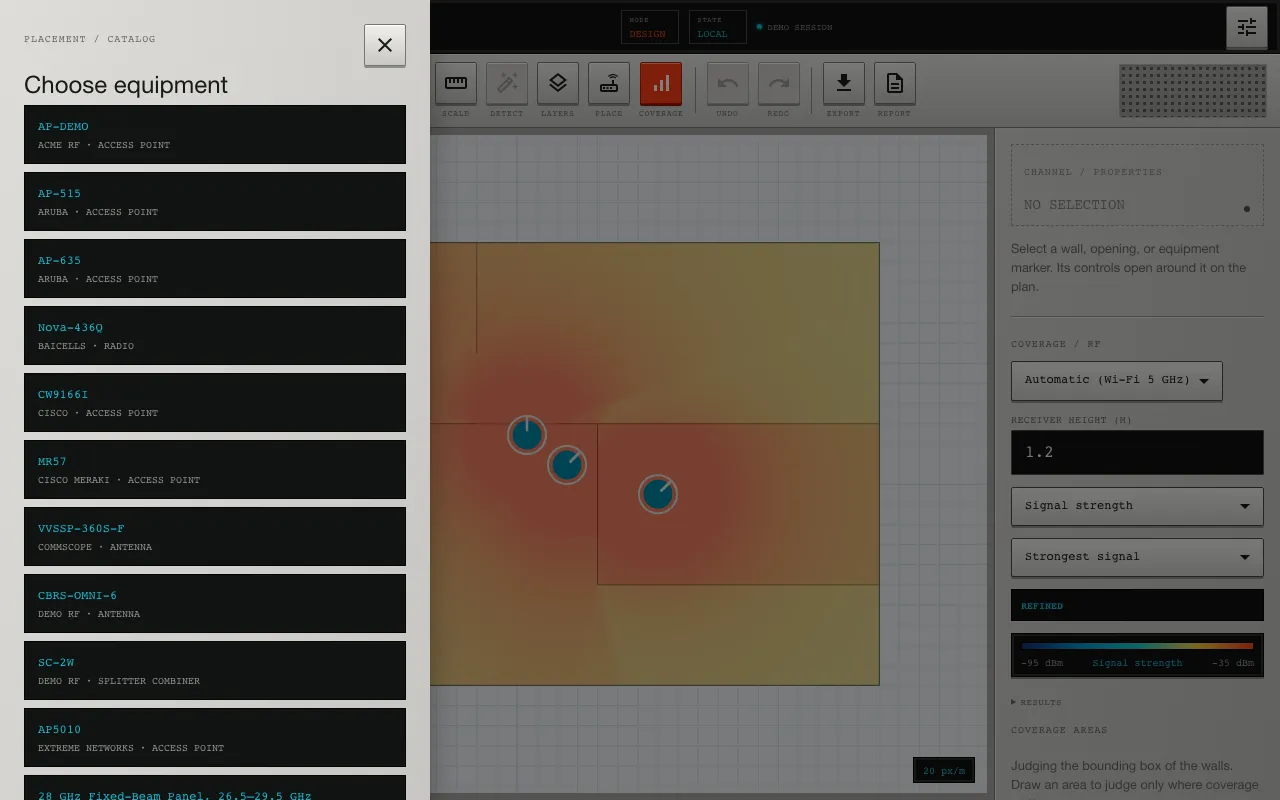
Open the equipment catalog and select the intended access point, radio, or antenna. Catalog records distinguish sourced manufacturer values from project-specific overrides. For a discrete radio, attach an antenna whose supported frequency range covers the radio’s frequency.
Directional antennas require a radiation pattern for the simulated band. If no compatible pattern is available, SiteRF reports the missing input instead of pretending the antenna is omnidirectional.
Place and identify the device
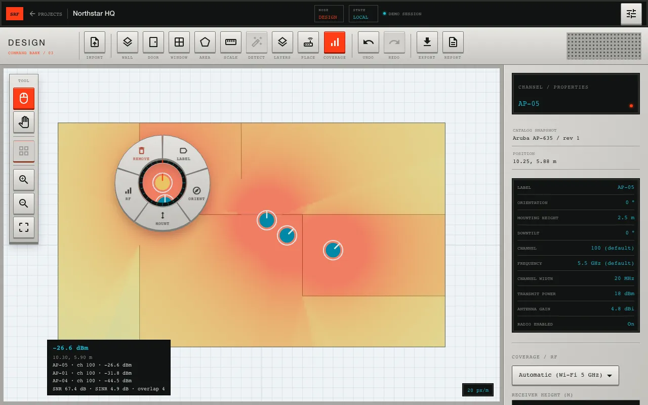
Place the device at its planned horizontal position and give it a label that remains meaningful in maps and reports. Set the mounting height relative to the calibrated floor. For directional equipment, confirm compass orientation and mechanical downtilt.
Configure each radio
Use a channel and bandwidth combination supported by the selected radio profile, or enter a raw center frequency for a generic scenario. Do not set both a channel and an independent center frequency for the same radio.
Review:
- enabled or disabled state;
- protocol and operating band;
- channel or center frequency;
- channel bandwidth;
- transmit power in dBm;
- antenna gain in dBi;
- mounting height, azimuth, and tilt.
Transmit power and antenna gain are logarithmic quantities. A 3 dB increase approximately doubles radiated power; it does not double coverage distance in a real indoor environment. Use the link-budget calculator to separate EIRP, path loss, and receiver power.
The same properties panel carries this radio configuration: channel, frequency, channel width, transmit power, antenna gain, and whether the radio is enabled — each editable per placement, independent of the catalog default.
Treat overrides as engineering decisions
An override should describe the deployed configuration, not make the heatmap look better. Confirm regional power limits, device configuration, cable loss, antenna specifications, and installation constraints outside SiteRF. Record important assumptions in the report.
After placing equipment, proceed to Calculate and read coverage.