
Coverage quality starts with geometry. SiteRF treats the imported drawing as a spatial model, so an incorrect scale or an irrelevant line can affect every computed distance and wall crossing.
Prepare the DXF
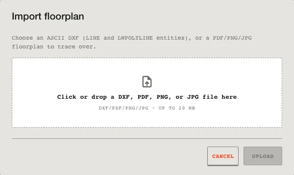
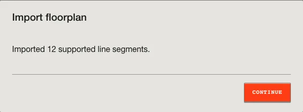
Export an ASCII DXF containing the floor you intend to model. Keep the useful wall and opening layers; remove distant title blocks, legends, and unrelated site geometry when practical. SiteRF reads supported two-dimensional entities and reports unsupported or malformed content instead of silently treating it as RF structure.
The importer rejects empty or excessively large drawings. If an import fails, correct the source rather than converting unknown geometry into a screenshot.
Confirm units and scale
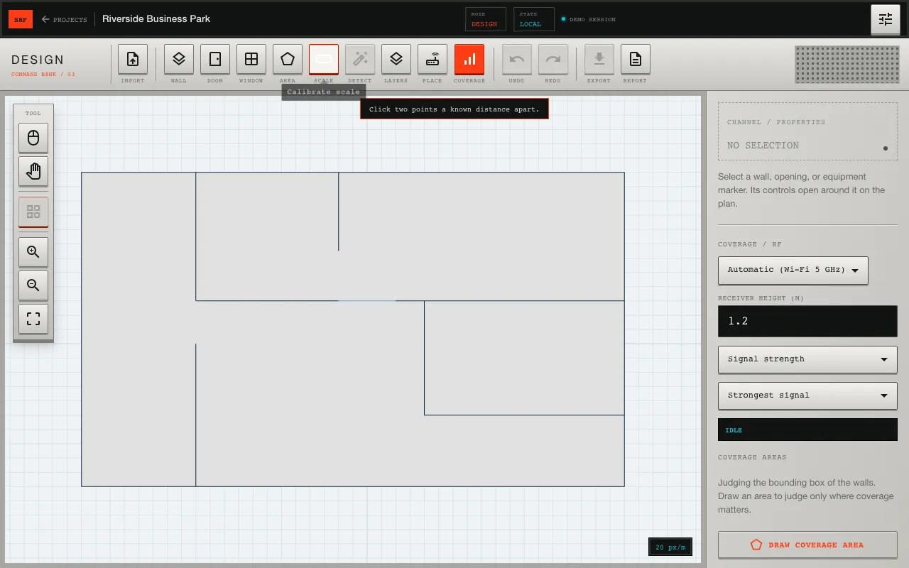
When the file declares a recognized unit, verify it against a known span. When units are absent or ambiguous, use the calibration tool:
- Choose two points whose real separation is known.
- Enter the measured length and unit.
- Confirm that the resulting plan dimensions are plausible.
A two-times scale error produces a two-times distance error. Because path loss is logarithmic, the error does not appear as a simple two-times change in dB; it also changes which boundaries a path encounters.
Decide which lines affect RF
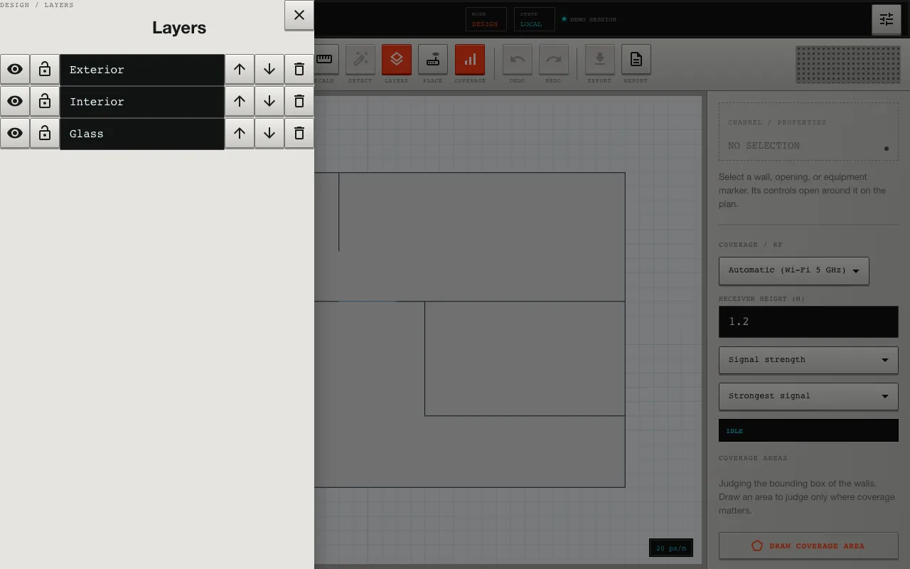
Imported layers remain distinguishable. Use that information to separate structural walls from furniture, annotations, ceiling grids, and other drawing detail. A visible line is not automatically an RF boundary.
For every RF boundary, assign a material from the supported library. SiteRF uses explicit transmission and reflection loss values resolved for the simulated band. Layer-name suggestions are only suggestions; verify them before calculation.
Model doors and windows as openings
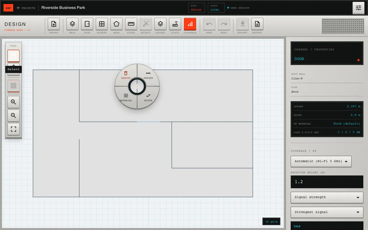
An opening replaces a span of its host boundary. Do not leave the original wall active behind the opening or draw a second overlapping boundary: either mistake double-counts or incorrectly preserves the solid wall. Assign the opening material when glass or another attenuating surface remains.
Review before equipment placement
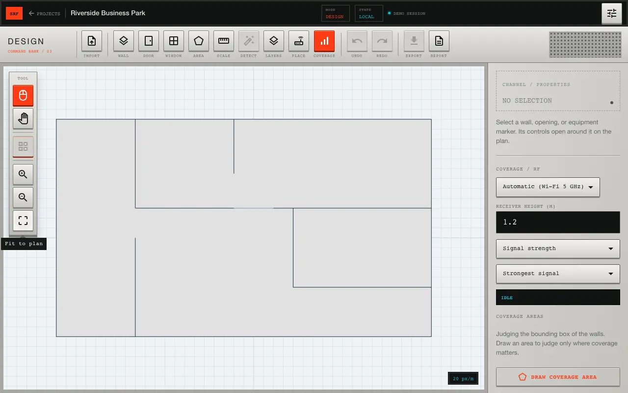
Check the exterior outline, important interior partitions, coverage areas, and known openings at a useful zoom. Confirm that the project origin and extents contain only the intended floor. Save a new floorplan revision after corrections so later results can be tied to the geometry they used.
Continue with Place and configure RF equipment.